Diesel engine is widely used in the field of commercial vehicles because of its high power, low fuel consumption and high combustion efficiency. At present, the electronic control technology of diesel engine is mainly divided into three kinds: position control, time control and time pressure control. The tics system carried by the 6HK1-TC series engine of Isuzu heavy truck is the abbreviation of timing & injection control system. As the representative of the position control type of the first generation diesel engine electronic control system, it is a product developed by Isuzu Motor Company at the end of the 20th century. The system takes the control unit ECU as the core to automatically control the fuel injection quantity, fuel injection timing and fuel injection rate, so as to meet the requirements of various working conditions of the engine.
1. Composition of tics system
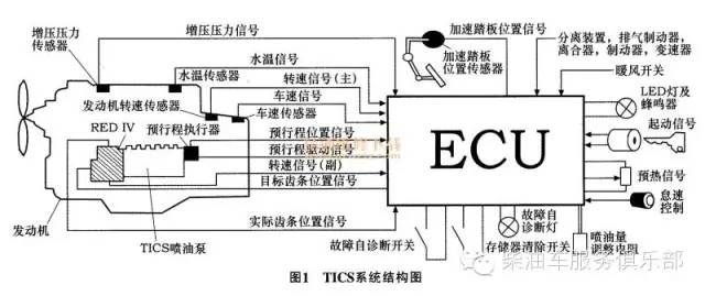
The structure of tics system is shown in Figure 1. Isuzu electric control tics system is divided into mechanical part and circuit part. The mechanical part is mainly an injection pump with red IV electronic governor and pre stroke actuator; The circuit part is composed of an electronic control circuit composed of ECU, various sensors and actuators. The input signals of the circuit part mainly include engine crankshaft speed sensor, throttle position sensor, water temperature sensor, intake pressure sensor, vehicle speed sensor, rack position sensor, pre travel position sensor, etc. Through the input signal of the circuit part, the ECU calculates through the preset program and outputs the command to the actuator, so as to change the working condition of the engine. The actuator mainly includes pre stroke actuator, red IV electronic governor, etc.
The main features of tics system are: while maintaining low fuel consumption of direct injection engine, improving emission performance and reducing NOx emission; ECU controls the electronic governor to adjust the oil quantity according to each working condition; Without a timing device, the electronic pre stroke actuator can control and change the injection timing and injection rate at the same time; Increase the advance angle during cold start to improve the starting performance; At the same time, the self diagnosis system of the system is also convenient for troubleshooting.
1.1 tics fuel injection pump
Tics fuel injection pump adopts the traditional in-line plunger pump body. The main parts of the pump body are plunger and plunger sleeve, camshaft, roller body, plunger spring, rotating sleeve and ring gear, oil outlet valve and valve seat, compression pipe connection, etc. The difference is that a timing sleeve is arranged below the plunger sleeve to control the change of pre stroke through the up and down movement of the timing rod. The so-called plunger pre stroke refers to the stroke from the bottom dead center of the plunger to closing the oil inlet and outlet holes connected with the oil storage chamber, or the cam lift before the plunger starts to pressurize the fuel during the upward process of the plunger. In addition, the inlet and outlet of tics fuel injection pump are set on the plunger, which is different from that of general fuel injection pump, which determines that the fuel injection process is different from that of ordinary fuel injection pump. Its working process is divided into three main processes: oil inlet, oil pressure injection and stop injection.
1.2 red IV electronic governor
The structure group of redw electronic governor is: linear DC motor, control rack, rack position sensor, connecting rod, stop rod, shell, etc. Its structure is shown in Figure 2.
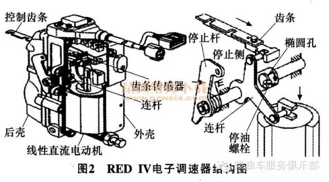
In terms of working principle, red IV electronic governor is composed of input part, control part and execution part. The signal sent by the rack position sensor is used as the input signal, which is converted into digital signal through analog-to-digital converter (A / D), and then transmitted to the control part. In the control part, the input digital signal is compared with the data stored in ROM, and the execution parameters obtained by comparison are transmitted to the execution part. The linear DC motor acts according to the execution parameters, so as to push the coil up and down, that is, drive the rack to move horizontally, and adjust and control the amount of fuel injection. In addition, when the stop lever is operated, the stop lever drives the rack to move to the oil stop direction to ensure that the stop lever can shut down the engine in any emergency.
1.3 electronic pre stroke actuator
The electronic pre stroke actuator is mainly composed of pre stroke sensor and actuator. The ECU judges the actual fuel supply timing according to the signal of the timing sensor, compares the theoretical parameters of the engine under various working conditions in real time, and then outputs the timing control signal to make the timing actuator act, control the up and down movement of the timing sleeve, and change the relative position between the plunger sleeve and the plunger in the fuel injection pump, that is, change the effective stroke of the plunger, so as to change the fuel injection timing.
2 tics system circuit diagram
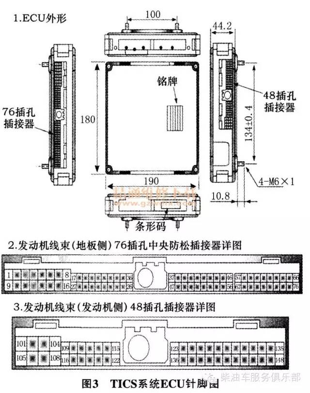
The wiring diagram of ECU (pin 3) and system (pin 4) in the wiring diagram. Through the system circuit diagram, we can quickly identify the electronic and electrical components in the circuit diagram, understand the working mode of each sensor and electronic actuator, and systematically judge the possible fault position according to the circuit diagram of the electronic control system. As the core of the whole electronic control system, ECU monitors all electrical circuits and electrical components of the vehicle in real time, and can make timely adjustments to any situation. Combined with the system ECU pin diagram and the system circuit layout, it is convenient to detect the working condition of each circuit of the system, judge whether the on-off is good or bad and whether the internal program of ECU runs normally.
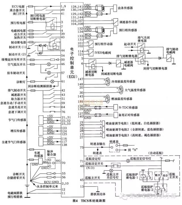
The current of all electrical components in the system circuit diagram starts from the positive pole of the power supply, rises the electrical components to ground through the fuse leaf switch, and then returns to the negative pole of the power supply to form a loop. The tics sensor circuit and drive circuit are included. Switch circuits mainly include: clutch switch circuit, throttle switch circuit, power switch circuit, heating switch circuit, brake switch circuit, slow return garage switch circuit, air low-pressure switch circuit, brake switch circuit, etc. Sensor circuits mainly include: throttle sensor circuit, boost sensor circuit, coolant temperature sensor circuit, atmospheric temperature sensor circuit, fuel temperature sensor circuit, rack sensor circuit, pre travel sensor circuit, etc. The driving circuits mainly include: exhaust brake solenoid valve circuit, governor actuator circuit and pre travel actuator circuit. In addition, tics has a self diagnosis system, which is also a separate loop.
ECU usually adds a 5V low-voltage reference signal to the sensor. The sensor converts the changed resistance value into a voltage signal through variable resistance and returns it to ECU. ECU monitors the working state of the sensor through the change of feedback signal. The switch circuit can be regarded as a special sensor signal. The actuator controls the drive circuit according to the instruction of ECU. The actuator of tics electric control system is composed of induction coil. ECU changes the actuating force of the coil by changing the current flowing through the coil, so as to change the action of the actuator.
3. Troubleshooting of tics system
3.1 example 1
Fault phenomenon: the engine power is insufficient, the speed limit is limited, that is, the throttle is added to the maximum position, and the maximum engine speed is only 2200 R / min. First, retrieve the fault code through the professional decoding instrument and display the fault code "292". There is an open circuit or open circuit fault of the pre travel actuator. Secondly, check the resistance values of the six terminals of the pre travel actuator socket (6 pins, gray) with a multimeter. It is found that the resistance values of the six terminals in the connecting plug are infinite, indicating that the pre travel actuator has been burned out. After replacing the new pre travel actuator and adjusting the initial parameters, the fault is eliminated and the acceleration is normal.
3.2 example 2
Fault phenomenon: the same is that the engine power is insufficient and the speed is limited. First, retrieve the fault code through the professional decoding instrument to show that the power fuse of the pre travel actuator is blown. By detecting the power circuit of the pre stroke actuator, that is, from the battery live wire to the fuse, to the relay and then to the ECU pin, it is found that one section of the circuit from the fuse to the relay is burnt out due to wear and grounding. Reconnect and repair, and the fault still exists. Further test the pin of the pre travel power cut-off relay of the ECU. It is found that there is no level change of this pin when the ECU is powered on, resulting in the non action of the pre travel actuator power relay. After replacing the new ECU, the fault is eliminated and the vehicle acceleration is normal.
3.3 example 3
Fault phenomenon: the engine stalls when accelerating during driving. First, retrieve the fault code through the professional decoding instrument and display that there is no fault code. Check that all circuits are normal and ECU has no fault. The fault diagnosis without fault code generally focuses on the mechanical part. Since it is a fuel system fault, it should be checked from the fuel circuit. The inspection from the fuel injection pump in the cab found that the mechanical flameout line did not return to zero under normal conditions. Readjust the length of the flameout cable to make it return to zero. Finally, the fault is eliminated. There is no sudden flameout during acceleration during driving.
4 Conclusion
As the first generation of electronic control system, tics system still occupies a certain market share in electronic control engine because of its simple structure, small changes to the traditional mechanical engine control system, high control accuracy, fast response speed, economy and environmental protection. For the maintenance of the system fault, it is necessary to systematically master its structural composition, ECU control principle and circuit conditions of various working conditions of the engine, give priority to troubleshooting the faults of relevant components displayed by the fault code, and carefully eliminate the pure mechanical faults in the state of no fault code at the same time.